Microchip 900164000732332
If Google brought you here looking for a microchip in a dog, you have found our collie Merlin. Please contact us by e-mail at ens AT ix.netcom.com
Tikkum Olam Makers: an assistive technology make-a-thon
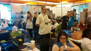
Near the end of July, I took part in a very special maker event. For three days Nova Labs devoted itself to creating assistive technology solutions for individuals with disabilities, under the guidance of Tikkum Olam Makers (TOM). Tikkun Olam is Hebrew for “repairing the world”, and TOM’s approach to this is to bring together makers, an individual with a unique challenge (the need-knower), and experts in related fields such as medicine.
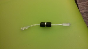
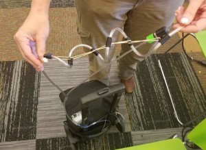
I was part of a three-person team, with Nick Sipes and Sarah Pickford. We had some options as far as which project to work on. The project I put on high on my list, and was assigned to, involved creating solutions for individuals who need oxygen yet are still mobile. Delivering oxygen involves a fair number of long tubes, ultimately running into the user’s nose, and it is easy for the tubes to get tangled and stuck if one moves around. By nature, most TOM projects are very individual and meant for situations where the need-knower may be the only one in the world with a particular problem. But for this, it seemed there might be more general applications.
For preparation there were courses offered for TOM participants. I took advantage of this to learn OnShape, a fantastic free online CAD program that was apparently built by the same engineers who made SolidWorks. Bruce has been telling me for a long time that no free tool could live up to SolidWorks, but a few thousand dollars seemed rather high for what I was doing. OnShape does indeed blow away the other tools I’ve used, and for this event it was particularly useful to be able to collaborate with my team in creating parts and assembling them.
Makers love to feel we are working on something with a purpose, and the energy level at Nova Labs was quite high. In addition to the official teams, a large number of mentors were available to help with tools, many journalists and researchers observed and interviewed us, and an incredible array of helpful people who did everything from loaning equipment to running out to Home Depot. There was a lot of food and coffee available at all times. There were also journalists and researchers covering the event itself. There were visits from various federal departments as well. (Now that it has been a few weeks, some of the names elude me.) In short, the publicity was excellent.
Most of my days went from 9AM to 10PM. However there were many teams who worked around the clock; some of them had some incredibly challenging projects that were not really possible to finish in 3 days. Still, they got a solid start and some of them have continued working.
Our team ended up with three “products”. As requested, we published these on the TOM site, however, it has proven impossible for me to edit anything we placed there, and the Microsoft Word format was almost unusable. I’m told it’s under development. In the meantime, we decided to publish our work on Instructables for everyone’s benefit. The links are below.
This was a great deal of fun and I would enjoy doing it again. I hope that the organizers consider teaming with Instructables or a similar platform to bring the results to a wider group of users; right now that seems to be the greatest limitation.
Programming the Arduino with the Eclipse IDE
Back when I was working on my firefighting robot, I wanted a better system than the default Arduino IDE (integrated development environment). With dozens of files and thousands of lines of code to manage, a professional development environment became highly desirable. I blogged previously about moving my Arduino code into Eclipse.
On November 19, 2013 I led a class at Nova Labs on Programming the Arduino with the Eclipse IDE. The link will take you to the PDF version of my talk, and it should be sufficiently detailed for anyone who wishes to do this task. We had quite a good turnout even though the class had a fee — apparently I am not the only one frustrated with the regular Arduino IDE!
For readers in the MD/DC/VA area, please check out the NOVA Labs Meetups which are open to the public. We welcome new members and the tools and expertise here continue to impress me. On January 23 we are doing our first Women in Engineering meetup. I don’t exactly know what this is yet (even though I’ve been volunteered as an event organizer…a little surprise there) but I do know there will be quite a few interesting women to meet.
Working in 2D: Using a CNC Mill
I have been enjoying the 3D printer. It’s very easy to go on Thingiverse and download toys and objects to print. My ultimate goal, though, is to design my own parts for the machines I want to build. And that means learning computer-aided design (CAD) software. There are quite a few of these around for hobbyists: SketchUp and OpenSCAD for example. But generally I hadn’t fallen in love with any of them. They were either imprecise or hard to use with complex objects.
In my continuing search I came across a great free program: DraftSight. It’s made by the same company that own SolidWorks, a premiere (and extremely expensive) software CAD package. DraftSight has one key limitation, it can only do 2D. Still, this seemed a reasonable place to start, especially as so many 3D objects are simple extrusions of a 2D design. And I thought this would be a good excuse to finally make something on the Nova Labs laser cutter, which can cut out precision pieces from a number of materials.
For project ideas, I turned to the Robot Builder’s Bonanza. I’d seen the Hexbot robot in there and thought it would be a cool, straightforward build. I’ve always wanted to make something that walked instead of rolled. The author Gordon McComb suggests working with expanded PVC, also known as Sintra. It has most of the advantages of wood while appearing in bright colors and very uniform, which makes it easy to machine. I had used this material as a base for FireCheetah and it had attracted favorable comments. I ordered a slab and started designing.
The software worked very well and it was good to finally have a program where I could type in exact dimensions (Inkscape, the recommended program for the laser cutter, sadly lacking there). The design phase went quickly. When I went to cut, however, I discovered a problem; PVC cannot be used in a laser cutter as it gives off chlorine gas. I already knew that the laser cutter could not handle metal, either, which was a great disappointment.
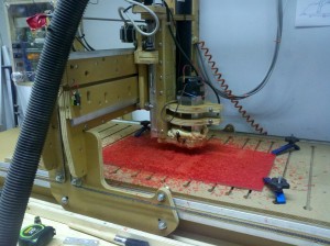
Fortunately, Nova Labs has a nice, large, CNC mill. CNC stands for “computer numberical control” and a CNC mill is one of the classic machine tools. To quote from the ShopBot site, a CNC mill:
is an amazing do-all tool for precisely cutting, carving, drilling or machining all kinds of things from all kinds of materials. You use the included software to design your parts on your personal computer, then, like a robot, the computer controls the cutter to precisely cut your parts.
A CNC mill is a perfect compliment to a 3D printer. The 3D printer is an additive machine, creating parts by laying down material; the CNC mill creates parts by taking away material. And unlike the laser cutter or 3D printer, the CNC mill can work with almost any material. Clearly, a valuable tool to learn about.
The downside is that the learning curve is steeper than a laser cutter; when drill bits are involved the danger level rises and there are more variables to tune. And unlike the laser cutter, there were no training classes set up for it. Fortunately a fellow maker, Neil Moloney, was kind enough to show me the basics.
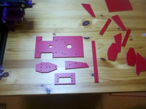
These are the robot pieces I cut:
The CNC mill drilled the screw holes and cut the edges beautifully. Far better than I could ever have done by the manual methods suggested in the book.
Ironically, though, when I went to put the pieces together I discovered that the original plans were flawed; there is not enough clearance for some nuts. I designed perfectly to a poor schematic. No tool can fix that! So in the end I will have to pull out my scroll saw and do a minor amount of manual trimming. Nevertheless the CNC mill is a fantastic tool and I’m looking forward to using it again.
Building a 3D Printer
For a while now I’ve been working to upgrade my toolset, in order to make more interesting robots. One of the projects is 3D printing. Today I’m happy to report the completion of a milestone: I am the proud owner of a home-built 3D printer!
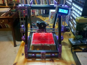
My MendelMax 3D Printer. At this point it was 90% done; I have since added lights and tied up the wires.
There are so many choices when it comes to 3D printers, that I was nearly paralyzed in moving forward on the project. Then one day the Nova Labs 3-D printing group announced a group build. For $750 we would get the parts for a $2,000 printer (a variant of the MendelMax 1.5), and assemble it ourselves with help from the group. I hesitated a bit — I suspected the build might be rather involved — but I also knew that, claims from MakerBot notwithstanding, there really is no such thing as a great “out of the box” 3D printer. If you want your printer to do well, you have to know how the machine works, and getting your hands dirty is the best way. Having expert guidance was a significant bonus.
So I joined in, and after the usual delays of hackerspace group buys, we started building. I was a little dismayed to find there were no written directions at all! Just a few YouTube videos for a related model, which only covered the hardware part of the build. That meant I had to come in to Nova Labs on Monday or Tuesday to join the build group; I couldn’t do much at home. Sometimes this was inconvenient, but I got to know some great people, all of whom were extremely helpful. Brian Briggman in particular went out of his way to show up at every build meeting and helped dozens of us complete our printers.
There were some difficulties along the way. Some of the frame pieces, being custom, either didn’t fit right at first or needed slightly longer screws. Then I screwed in the RAMPs board too tightly, causing a short — this did not cause permanent damage, fortunately. My first print was a little hairy, as the hot end thermistor had quietly detached itself, and we were therefore heating up the PLA until it smoked. As I was the first person to try printing with PLA, we didn’t know that wasn’t normal! (After that I went through and added strain relief to every wire.)
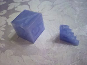
But after the thermistor adventure, I got some successful prints almost immediately — and this is without calibration. Here is a picture of my Futura die, and a 5mm calibration cube pyramid:
I have some work left to do. The printer bed is (pretty much) level now, thanks to some washers. I need to confirm the x and y stepper motors are moving the right distance per step. Then the extrusion rate must be calibrated, and this varies with different filaments, so will need to be done many times in the future.
In many respects the biggest challenge is software. If I want to go beyond printing items off of Thingiverse I must learn to to design my own objects. There are many programs for doing 3D CAD design, but one must take the time to learn how to do it, and the options for hobbyists are generally not user friendly. I’ve looked at a few. (It’s worth mentioning here that I found an outstanding free 2D software CAD program, DraftSight. I am told it is a clone of AutoCAD.)
After the 3D design is done, it’s often necessary to manipulate the files to get them to work properly for printing. So I am also learning about slic3r, netfabb, and Repetier-Host.
Lots of fun ahead!
FireCheetah returns to Abington
Saturday was the Abington firefighting competition. I had entered this contest last year with very little time to prepare, and was looking forward to trying again. I made considerable progress (as blogged here over the past few months), and showed up with a robot that was stronger and simpler. Most importantly, it was smarter.
Tests had gone very well at home. Audio start, full navigation of the maze, blowing out the candle, and the crowd-pleasing return to start all functioned reliably. So our drive to Philadelphia Friday night was relaxed and I slept well. The kids had a robot also, a LEGO Mindstorms creation named Dark Lord who used a sponge to extinguish the candle. (Dark Lord is white in color so I don’t understand the name.)
On Saturday I showed up as early as possible to calibrate, get ready, and talk with the other roboticists. First step, attach the battery and power on the robot. Except…it wasn’t powering on. Battery was fully charged, as was the spare, and neither worked. After some increasingly frantic work with the voltmeter, I realized that one of the wires on my main power switch had snapped. The switch had worked well for over a year. Fortunately I had a soldering iron and extra wire with me; unfortunately, I did not have a third-hand. Paul Boxmeyer of Lycoming Robotics was kind enough to loan me a clamp but it was still very difficult to attach a wire to a small switch without shorting the terminals. Not fun. Eventually though, I fixed it. And then discovered that the other wire had snapped.
I did fix the switch, but this consumed a tremendous amount of time. Next step, calibrate the sensors. IR was basically the same as at home since I had white walls in my maze. The candle, however, was another matter. When I came in Paul took a look at my robot and expressed surprise that I didn’t have an adjustable potentiometer. That was a prescient remark. I found that I had trouble seeing the candle in the maze room, no doubt due to all the fluorescent lights. Still, boosting the threshold level in software allowed me to see my practice candles from the necessary distance.
I finally had time to do a practice run. The official candles were much thinner than mine, but I succeeded in the quick single-room test and hoped for the best. Alas, it was not to be. In the first official run, the robot went smoothly to the room, looked for the candle, and left it burning there. It simply couldn’t see it. Later Paul explained to me why my circuit had failed; I would have been better off with only one photodiode rather than four in parallel. They really act like transistors. And a pot would have allowed for better tuning.
For the second run, I knew I would miss the candle, so I asked the judges to put the candle in the fourth room so that I could show off the navigation. My proudest moment was watching the robot pirouette through the first three rooms. Its movement was so beautiful. The carpets were far thinner than I had remembered and the robot barely seemed to notice them; the ones I had at home were much more difficult. On the fourth room — I discovered that my home maze construction had an error. I was 4″ off spec, and Saturday’s maze was another 3″ off. With that, the robot was too far over and scraped a wall, forcing a turn. The recovery code kicked in and kept FireCheetah moving, but with misinformation of its location the robot could not do anything useful. This run was quite frustrating. If I’d had the time to do one full practice run, I would have seen the problem and fixed it with a simple edit. But the switch chose a bad moment to fail.
This year I had more time to watch the competition itself, and it was quite enjoyable. You really empathized with these little creatures and wanted them to succeed. Some were more interesting than others. As I feared, the no-carpet option meant that a lot of robots went for dead reckoning, and that is a bit dull in my humble opinion. Others bumbled around in a charming way. Many of them had trouble, as I did, finding the candle. Or in putting it out. Once again I am convinced that a fan is the way to go. So many sponges, balloons, and other exotic methods failed to work. Almost all other robots there were kits: Vex, LEGO, Boebot, and Paul’s students used his standard base. One woman came up to me later and said she thought my robot was the cutest, which was quite nice of her. They do begin to feel like pets after a while.
The kids’ robot did very well, which was no surprise. Oh the reliability of remote control! They had some competition this year with another girl who also had a LEGO robot. Since their division was untimed, everyone got a trophy anyway. Paul won the Senior Division, along with several other awards for innovation including the multi-robot division where he was unchallenged. One of his students won the Junior Division as well. Note, she used a fan. The other students used sponges, most of which failed.
Steve Rhoads and Foster Schucker from the Vex robotics club were there also, and this time we successfully exchanged contact information. They are cheerful guys and I enjoyed seeing their new Arduino-based robot. They are trying to use Arduino while still retaining kit-level reliability — no home soldering here — and it’s an interesting challenge. They have found a very nice IR grid sensor and I look forward to seeing that at work. Best of all, they are planning to hold some firefighting competitions this summer. I am happy to hear this because I would like to succeed next time, without waiting an entire year, and cross it off the list.
Obviously, I need a better way to detect the candle. Paul suggested that my circuit could work with some tweaks, and that’s probably true, but fiddling with pots is not what I want to do. Since I don’t have the same type of lighting at home to test with I want something more reliable, and that means spending more money on a better sensor. One option is the UV Tron, at least for detection. At the moment I am considering the MLX90620 thermopile. Interfacing with it is something of a software challenge, and it could provide continuous directional feedback as the robot approaches the candle.
Preparing for a competition is very intense and after it is over there is always a letdown. What to do next? In firefighting, I could go well beyond the thermistor; it would be very easy now to shrink the robot significantly, always good when navigating a maze. I still have a ton of I/O from my Mega clone, and could add more sensors. This would allow better obstacle detection. My second run failed due to a wrong number that was hard-coded. I didn’t have many of them, but there were a few. A great robot would not need any of that, it could center itself as it approached a new hallway. Heck, it would be possible to slap an Asus (Kinect clone) on the robot, it fits the size limitation. An exotic candle extinguisher (with a fan as backup!) gets extra points. Or maybe it would be fun to make a walking robot — something completely different.
Beyond firefighting, there are a number of challenges at RoboGames that look fun. The space elevator robot or table bot would all be very new. I like the creative aspect of these and they are less pass/fail than firefighting — which is another contest option at RoboGames.
I’ve ended up with some nice C++ code for any differential drive robot. It’s already on Github but I need to separate it out from the firefighting class to make it of general use. There is a local robotics hackathon on Sunday so maybe I will have it ready by then. The link will be announced here when it’s done.
Here is a video of the one successful run I did in the official maze. Go FireCheetah!
Ready to put out some fires
Finally the time has come — the Abington Firefighting Competition is two days away. FireCheetah is tested and ready to go! The kids have their own robot this year, a LEGO Mindstorms creation named Dark Lord, and he is looking good too.
All about sensors
With navigation mostly solved early on, there was more time to look at the sensor side of things. There is more to it than I initially realized. Take candle detection, for instance. I thought my homemade UV sensor was flaky due to varying values in the same location. Turns out that was due to changes in the abundant sunlight in my testing area. I added a sensor hood to reduce the effect, but even so the ambient UV level caused by the sun is significant. I need to change my threshold for fire detection by a factor of two depending on whether I am testing in the day or at night. (This caused some serious hair pulling until I figured it out.)
The sonar, also, has its quirks. Every now and then, a wrong value creeps in. This is particularly bad for times when I use the side sensors the line up with the wall. Both values need to be accurate. In the end I was able to resolve this by making sure that two subsequent readings for each sonar are consistent and within a valid range. If the result yields an alignment change of over 45 degrees I discard it completely, and resulting turns are capped to 30 degrees. It’s worth noting here that common sensor library functions like “take an average” or “use the median” don’t solve this problem.
IR sensors are famous for variability but strangely enough I have had few problems with mine. Still, the precise values for the maze walls on Saturday may be different.
I plan to spend most of my morning practice time in the arena calibrating the sensors, especially for the candle. I won’t line up for the maze practice until later. Last year many robots navigated the course successfully and failed to find the candle, which could certainly happen if I don’t calibrate properly.
And many things depend on battery level. I plan to run with a full battery, so that is what I try to test with.
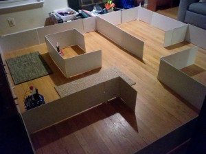
The sensor lessons confirmed the value of copious logging combined with repetitive testing. It’s a little boring — the kids told me many times, “Mom, your robot is done!” — but it’s the best way to drive out bugs. Below is a picture of the maze I used:
Audio start
Starting the robot with a 3-4 kHz sound, instead of a button, is good for a 20% time bonus. I figured this would be fairly simple, and I tried to build a circuit with an LM567 tone detector chip. Everyone says this is easy…well, after trying all the capacitors I had, and laying in a stock supply of new ones with all the right values, I never got it working. Plus, it was pretty darn ugly. Circuits with lots of components are just asking for trouble.
After two days of frustration I found a better way. With an electret microphone, a resistor, and an Arduino DTMF decoder library, the problem was solved. Honestly I hate RC circuits and analog electronics, not surprising that software worked better. This trigger has been flawless. Never a false start, and the robot responds to the tone before my ears do! I use the TrueTone app on my phone to provide the sound.
Putting out the candle
You get a 25% bonus for using something other than air to extinguish the candle. I am sticking with air, specifically a fan, because you get to try more than once if you don’t succeed the first time!
Returning to the start
Another 20% bonus is available if your robot returns to the start after putting out the fire. Also, it looks very cool. This turned out to be pretty easy. I already have a planner, so I simply needed to add a list of return path nodes from each room. When the robot enters a room, it saves the entry point coordinates. It moves around to get the fire out. Then it uses dead reckoning to find its way back to the entry point, facing the opposite direction.
This is the only time I use dead reckoning. Although I’d use it elsewhere in principle, the sensor methods proved to be more reliable. They are less sensitive to slip from carpets or variable maze dimensions.
Construction
Homemade robots are delicate things. Things can shake loose or move over time. I’ve done what I can to make things as solid as possible, but I will have to use a checklist before each run just to be sure everything is right. The left hub setscrew can come loose, it’s rare, but when that happens it’s a disaster.
The drive train can definitely get over the carpet now, unless the set screw is loose. Of course my carpets may not be the same as what is present at the competition, but from my old videos they look similar. And speaking of carpets…
A last-minute rules change
Yesterday all the contestants received an e-mail notice that carpets would now be optional in the high school and senior division, rather than required, due to “confusion in the rules”. What???
Last year, the carpets were harbingers of doom for many robots. So much so, that any robot who made it through twice was guaranteed a prize; and my design reflects that, with lots of sensor checks and — therefore — a slower speed. A carpet-free robot can use dead-reckoning and potentially be very fast. Of course, this is not the cutthroat world of Trinity. Nevertheless I suspect many teams will take this option and that means more competition.
Using the carpets does come with a significant time bonus, 30% off. That is not as great as the multi-room mode bonus (not a bonus exactly, you just avoid a 3 minute penalty). Unless I show up for practice and find the carpets far worse than my test ones, I will use the carpets. After all that is what I designed for and want to conquer, and what is life without some risk. Audio start, carpets, and return home combine to form a 0.45 factor applied to total time.
What’s a robot blog post without some video? Here is FireCheetah navigating the full mockup of the Abington/Trinity maze, putting out the candle, and returning home. One take, I swear.
Whatever happens on Saturday, preparing for the competition was a wonderful experience and I learned a great deal. I’m looking forward to seeing some of the people I spoke with last year. This time I hope to relax and enjoy and watch more of the competition.
More robot software improvements
The Abington firefighting competition is one month away. I’ve been working hard on the controller software, and at this point FireCheetah reliably navigates on continuous surfaces (floor or rug). That is well ahead of where things were last year! Along the way I came across a few things that may be useful to other roboticists.
A better ping library for ultrasonic sensors
There are quite a few Arduino libraries out there for ultrasonic sensors. They are important for this robot, as a key loop involves driving forward until we are a certain distance away from a wall. Ultrasonic sensors work via echo-response, sending out a ping and waiting to see how long it takes to come back. Usually that happens fairly quickly, but if there are no obstacles within the range of the sensor, the code will keep listening until it times out. It turns out that the library I was using before had a fixed timeout value of one second(!), from the Arduino function pulseIn. One does not want a robot running a full second without any feedback. Pretty poor library design, as pulseIn allows you to customize the timeout value.
I stumbled across a far better library, NewPing. The home page lists its advantages:
- Works with many different ultrasonic sensor models: SR04, SRF05, SRF06, DYP-ME007 & Parallax PING)))™.
- Option to interface with all but the SRF06 sensor using only one Arduino pin.
- Doesn’t lag for a full second if no ping echo is received like all other ultrasonic libraries.
- Ping sensors consistently and reliably at up to 30 times per second.
- Timer interrupt method for event-driven sketches.
- Built-in digital filter method ping_median() for easy error correction.
- Uses port registers when accessing pins for faster execution and smaller code size.
- Allows setting of a maximum distance where pings beyond that distance are read as no ping “clear”.
- Ease of using multiple sensors (example sketch that pings 15 sensors).
- More accurate distance calculation (cm, inches & microseconds).
- Doesn’t use pulseIn, which is slow and gives incorrect results with some ultrasonic sensor models.
- Actively developed with features being added and bugs/issues addressed.
I immediately implemented the setting of a maximum distance, and the lag time went away.
The author had some impressive thoughts on why one should avoid using delay() in code.
Simple example “hello world” sketches work fine using delays. But, once you try to do a complex project, using delays will often result in a project that just doesn’t do what you want. Consider controlling a motorized robot with remote control that balances and using ping sensors to avoid collisions. Any delay at all, probably even 1 ms, would cause the balancing to fail and therefore your project would never work. In other words, it’s a good idea to start not using delays at all, or you’re going to have a really hard time getting your project off the ground (literally with the balancing robot example).
The NewPing library offers an event-driven mode, which I might try, though it is arguably more than I need and complexity runs the risk of adding bugs. The thinking here did inspire me to get rid of delays in all my PID loops — which get called over and over again from different pieces of code. Instead they do a check to see if sufficient time has elapsed before resampling and correcting. I have to think that once one goes down the road of balancing ball robots (which I’d love to do one day) a multi-threaded operating system is the way to go.
Of course, with all this, the biggest improvement I made with the sensors was discovering and fixing a bug from last year’s code: I had incorrectly used a tangent instead of sine. Now the wall alignment works every time.
Upgrading the Arduino avr-gcc compiler
When compiling my project over and over again in Eclipse, I always saw a strange warning: “only initialized variables can be placed into program memory area”. This was a little disturbing and eventually I decided to track it down. Turns out that the avr-gcc that ships with Arduino 1.0.3 is not the latest version, and it has bugs. Although I could have lived with the warning. I decided to upgrade after reading this post about the buginess of old avr-gcc with Arduino Megas. I had experienced the difficulties with global constructors that the author mentions. And so, I followed his directions to upgrade to avr-gcc 4.7.0 and avr-libc 1.8.0. I did not upgrade the Arduino IDE as I had a newer version than he did, but I did have to add
#define __AVR_LIBC_DEPRECATED_ENABLE__
to HardwareSerial.cpp so that it would compile correctly.
As I’ve mentioned before, developing on microcontrollers is not for the faint of heart. I don’t think I’ve ever had to upgrade a compiler in all my years of commercial software development. Ugh.
Carpet obstacles
The carpets in the competition are a challenge, as hitting one at a key point can cause the robot to lose track of odometry. This year I bought some carpet samples in the hopes of doing more realistic testing. As discussed on my previous post I redid the drive train with no gearboxes and the wheel base moved to the rear. Things are looking very stable. I am not ready to declare 100% success yet. It is particularly challenging to go from a polished floor onto a raised carpet. The Abingdon maze last year had flat rubber/carpet flooring, so much easier with the extra traction, but I don’t want to take any chances. Much more testing is required.
Once again software improvements are key. I now assume the carpet will toss the robot around and it may lose sight of the wall temporarily, but it is smart enough now to look around for a while with its sensors before giving up. As long as the robot can mount onto the carpet successfully, all’s well. Right now the left wheel is having trouble doing this from a smooth floor; that motor is slightly loose due to a missing retaining ring so I will replace it and see it what happens.
Making a robot go straight
If you create a mobile robot with a job to do, at some point you will be faced with the need to get it to a specific location. Firefighting competitions require the robot to navigate a known maze. Much of my limited time last year was spent trying to get FireCheetah to do the supposedly simple task of driving in a straight line. Sounds easy, right? For a differential drive robot with two wheels, just deliver the same torque to each wheel.
As it turns out, this obvious method doesn’t work very well. My robot did fine when I could hug a wall using sensors, which is most of the maze. Eventually, though, there are spots where it has to manage on its own. And there my robot had two big problems:
- It drifted left substantially, and
- On smooth floors it would skip to a stop, meaning that the final position was unpredictable
It was a maddening problem. Sometimes the robot would go where I wanted…and sometimes not. I tried a few things. I added a fudge factor to the motor voltages so the left side would go a bit faster. I tried a PID controller to even out encoder ticks — distance travelled — on the right and left side. I reduced the motor voltage, and therefore velocity, to minimize the skidding. But I couldn’t go too slow because I knew there would be carpets and the robot would not be able to move if the torque was too low. Heaven help me if I stalled the motors, because then the robot would be really unpredictable for the next hour. All in all not a situation to inspire confidence, and I knew going into the competition that I was unlikely to succeed in the autonomous task. (We were ultimately done in by an unrelated software bug introduced at the last minute.)
This year I was determined to solve the navigation problem early on. One step was upgrading the motors. These also came with better encoders, devices that tell you how much the engine shaft has rotated, and therefore how much the wheel has rotated. Ignoring slip, this gives you distance traveled. However, this did not solve the problem by itself — the robot still drifted left.
Time to put in some better software! My original code was loosely based on Mike Ferguson’s code for Crater, a winner at Trinity. He was dealing with far more limited processing power — he had an Atmel 168, I have a Mega — and so he had no PID of any kind. And indeed, in a fancier version of Crater he noted the problems with keeping the robot straight. I thought the answer might lie here.
As luck would have it, Coursera’s Control of Mobile Robots started up, and one of their examples gave me the solution. I am going to summarize it here, along with some extra details, for anyone with a differential drive robot. I won’t use their slides though, as they used a horribly confusing notation (sometimes v is angular velocity, sometimes linear, on the same page). Instead I recommend the following tutorial on differential drive kinematics. From there we get
where sr and sl give the displacement (distance traveled) for the left and right wheels respectively, b is the distance between wheels (from center-to-center along the length of the axle), and theta is the angle of the robot’s heading with respect to the x-axis.
With this equation in hand, we can rewrite our PID controller with the aim of controlling theta, the robot’s heading. In my case I simply used the proportional term. I chose a rational sampling speed based on expected period of encoder ticks. Almost instantly, the robot could drive straight! It was magical.
Along with this, I used PID for the overall linear velocity. That way I can move at the same moderate speed on all surfaces. The robot moves smoothly on a hard floor — and bumps up the torque to maintain that speed when it hits the carpet.
In the spirit of Mike Ferguson and other people who have shared their code, I am putting my libraries on GitHub so others can use them. I am not going to post the link just yet however, as they are under “active development” to put it mildly…
Physical reality intrudes
After delighting in these new capabilities for a few days, suddenly the robot stopped moving as reliably. This was a terrible time. I thought I might have introduced a software bug. Eventually I traced it back to my Faulhaber motors. These come with right-angle gearboxes and some of the set screws had gotten loose. This meant the motor shaft was turning but the wheels weren’t, or not always. Once the set screws were tightened, the robot behaved well again. This did point out one disadvantage of integrated encoders — I love them, but the external ones look at the wheel rather than than the motor shaft, and wheel rotation is really what we care about.
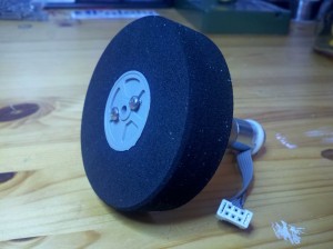
The gearboxes effectively extend the motor shaft, but are otherwise useless and add potential mechanical issues, such as play in the gears. I removed them from a pair of motors, which left only 3mm of shaft extending. However I found some narrow Polulu universal hubs that fit, and drilled holes in a pair of Lite-Flite wheels to attach them. The final product looks like this:
 |
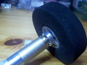 |
These have passed some simple tests but are not yet attached to the base. The base needs some reworking as well. I am using a platform from Budget Robotics which puts the wheels in the middle, and that means two casters for front and back. This platform was originally designed for a robot with skids and few motion requirements. Experimenting with some carpet samples has reaffirmed the principle that “three points make a plane” and it would be better to have only one caster — otherwise, it is easy for a wheel to get lifted off the floor and once that happens you are utterly dead. The robot thinks that side has moved when it hasn’t and the odometry is completely wrong. So I am going to attach the wheels further back on the robot, and cut off part of the base to do it.
Next steps
Although navigation is much improved, I do not plan to rely on dead reckoning. There are the carpets to worry about, and more fundamentally, a robot should use its sensors to adapt to the environment. FireCheetah has quite a few sensors and used properly should be capable of some robust recovery behavior. I will go through and confirm that “normal” navigation through the maze works — then time to have fun knocking the robot sideways and let’s see if it can get back on track.
Coursera, MATLAB, robotics, and 3D printing
The Heterogeneous Parallel Programming course at Coursera is more or less wrapped up. There were so many problems with the grading system that any “final resolution” has not been made as far as grades, and it is a little anti-climactic. I did very well on the assignments, but don’t know exactly what we get as far as certification, if anything. The final lectures were on a less interesting topic, and I skipped most of them. Overall though it was a great learning experience.
I did find some odd bugs. While on vacation, I was unable to access the Amazon cloud instance. No one else seemed to have this problem. I eventually discovered that if I VNCed into our corporate servers back in Maryland, I was indeed able to reach the instance. Apparently there is some sort of geographic filtering going on, perhaps to prevent multiple people from using the same Coursera or Amazon account? At any rate it did spur me to complete our corporate VPN.
There were some errors in the course material. This is inevitable and not a big deal. However there is so much noise in the discussion forums that it was hard to communicate with the staff. For obvious reasons the people with misgraded assignments or stuck on a problem were the loudest.
To a certain extent I am seeing similar greatness and problems in the new course I am taking, Control of Mobile Robots. The professor is engaging and this is wonderful material. However, one of the key summary slides has a serious error. For part of it, v is used as a linear velocity, then vr and vl are introduced — but they are angular velocity! This is never stated explicitly and does not make much sense. Since this is the reference page I’d normally use once the class is over, it’s a very annoying bug. Other students noticed it as well. However, it turns out that the TA lecture to walk people through doing the quiz also had an error, and far more people were screaming about that, and long story short I don’t think the slide will ever be fixed. Yet another misleading document to live on forever online…
That said, the material is marvelous and perfectly timed. This week included a broad overview of a robot behavior called “Go To Goal”, aka dead reckoning. This is exactly what I need to get FireCheetah going in a straight line when there is no wall to follow.
I am also taking Grow to Greatness: Smart Growth for Private Businesses, Part I which arguably is the most relevant to my real life. That, however, will be audit only. It is interesting but extremely verbose. One difficulty with streamed video lectures is that one can’t easily fast forward through the fluff. And this one has quite a bit of fluff.
MATLAB
It turns out that as a Coursera student (free enrollment), you can get a student evaluation of MATLAB for only $99, including several toolkits. This is an amazing bargain, as this software package can easily run over $1,000. MATLAB can solve math equations, plot data, and do many other useful tasks.
I have used Mathematica in the past, but the learning curve is quite steep and it’s easy to forget, so I never made much use of it once my thesis was done. With MATLAB installed, I see why it has become the default in the corporate engineering world. It has an easy to use GUI with lots of help, and they have some excellent introductory tutorials on their site. The command-line is there with all of its power, but you are not forced to use it all the time. This makes playing with data very, very easy.
For more details. see this page. (You may have to register for the course first.)
3D Printing
One of the biggest headaches on the hardware side of robotics is finding parts that fit perfectly. If you are not building from a kit, you generally wind up with special orders or hand-machining. I’ve acquired a few tools over the years for this, like the Dremel, a drill press, and vertical band saw; but I don’t have a mill or a lathe (they are heavy and a little dangerous with kids around). I recently took a course to use the Nova Labs laser cutter and that is a great tool for cutting out flat parts. But my machining in general is time-consuming and limited.
A few weeks ago I attended a DC Robotics meetup on hardware prototyping. And I was captivated by their 3D printer. This is a machine that extrudes melted plastic in a precise way to build a computer-designed model. If you can design it, you can (within limits) print it out. I have seen many 3D printers before, but this was the first time I could see the practical applications. Gears, shaft holders, brackets, all easy to create at home.
The printer at the meetup was from the best-known company, MakerBot. They have a very slick ad on YouTube:
My initial intent was to go out and buy one. However, after talking with more knowledgeable people and researching online, MakerBot has a poor reputation — partly because they have portrayed their machines as easy to setup and use. They are not. 3D printing is still experimental and requires extensive initial configuration, MakerBot more than most.
However, the latest generation of machines are at least stable once you have them setup. And then the printing is straightforward. It turns out that Nova Labs is doing a group build of the Mendel Max 1.5, and with the bulk purchase it will only be $750. Low price and expert help, who could ask for more? So I have signed up for it. No date yet but at the end I’ll own something like this:
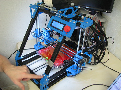
MendelMax 3-D printer
FireCheetah update
The new drivetrain is working very well. I’ve increased the clearance and FireCheetah is happily running on thick carpets all over the house, at only half the available power. Eclipse with the Arduino plug-in is working extremely well and certainly beats the old Notepad method.
I found a simple solution to the XBee crosstalk during Arduino updates. Since I don’t need any remote control for the robot this time, I simply hook up the Arduino transmission to the XBee reception — but not the reverse. No need for reconnecting wires or using a switch.
But I am the most excited about the software changes. Improved navigation is the key to success. If it works, that will be a post of its own, because I have found little useful information online.
