LED stair lights installed and working!
Just a quick post here, I want to let everyone know that the automated LED stair lights are in the stair wall and running successfully. Video to follow. As promised, I will be publishing the full schematic, code, and list of materials. Everything I used was off the shelf parts and chips, no PCB required. However, getting everything in the wall with the wires terminating somewhere sensible was a bit tricky. It’s complete now, though, and that’s a great feeling.
How to hack the bodybugg to work without a subscription fee
In my previous post I talked about the bodybugg and how I used it for body recomposition. Many people that look at the bodybugg hesitate due to the cost: first for the hardware itself, and second for the website subscription fee. The website displays those pretty graphs and totals that I showed earlier. More importantly, the bodybugg has a limited amount of memory on-board. The company has deliberately designed the product so that you must log on to their website in order to clear the memory. The subscription is not particularly cheap, either. It is $10/month, less if you pay in advance for extended period. I can afford this, but many people can’t.
There is a display watch that can show you the calories you’ve burned that day. So if there is a way to clear the bodybugg’s memory, it is possible to use the device without the website. Granted you lose those nice activity charts that show you what you burned each hour of the day, but having used the bugg for almost a year, I don’t need them. The “trip” function on the watch offers similar functionality in any case. The analysis tools in the website are absolutely terrible and of course you can’t export your data to a spreadsheet or anything useful like that.
I am not someone who believes “everything should be free” but this particular venture was inspired by a very negative interaction with their customer service. I got my bugg off of eBay, easy to do because eventually many people tire of paying the fees. It came with the previous owner’s remaining subscription. I was able to change gender, weight, etc. so it all worked fine for me. But, I couldn’t change the name on the account. Not a big deal. Recently I got a notice that my subscription was expiring. I figured at this point, as I was about to pay them directly, it would be fair to put my name on the account. I e-mailed them about this, and got a canned response saying that it was impossible to change the name or move my data — an obvious lie — and filled with dark hints about liability between users from sharing information.
That made me pretty mad. A few folks at HacDC had suggested I might be able to find some APIs for the device. And sure enough, I found something that would do exactly what I need. God bless the internet. An unsung genius has created the bodybugg command-line tool. It not only clears the memory but allows you to pull data off the device into various formats. You need to install Python and some related libraries; fortunately you do not need to know how to use Python.
If you follow their directions, be sure to read the comments as well. As a Windows user, I found it necessary to do the additional steps listed there: installing the Python serial library (with the installer), and editing the script to add a ser.close() command.
The clear functionality certainly works, after using it and going back to the website, the site thinks I had the bodybugg off and asks what I was doing during that time. That also reset the watch to a lower value, perhaps because the web site triggered a manually overwrite of what was in there.
I have 6 days left on my subscription. I may end up renewing after all, but it’s good to know that there is another option.
Living with a Bodybugg: Lessons in calories, metabolism, and weight loss
In August of 2010 I purchased a Bodybugg in order to help my weight loss efforts. The Bodybugg measures calorie burn. By pairing it with a food log, I was able to figure out how to make calories out greater than calories in. I have been wearing it ever since for maintenance, and it’s done a great job there too. During the time I’ve owned it I learned a lot about how my metabolism works, and had a chance to do some interesting experiments.
Last night I presented a talk on the Bodybugg at HacDC as part of a Quantified Self meetup. The meetup was surprisingly well attended, with over 20 people, and there were many good talks. It ranged from people who had written their own apps and gotten 30,000 users, to a clever fellow who boosted his pullup metrics with just paper and stickers. (If the last item sounds interesting, I highly recommend checking out a similar free website, Joe’s Goals. Very simple way to create or break habits and IT WORKS.)
I haven’t given a PowerPoint presentation in…decades? Didn’t particularly want to pay Microsoft for the privilege, either, so I downloaded OpenOffice and used their presentation software. It’s remarkably good. I then exported the slides to PDF, a universal format which I was confident would be supported by the presenter’s computer. And it was. All in all, much less painful than I feared it would be. I notice that Oracle now sponsors the Open Office project, no doubt they are delighted to deny their enemy a customer.
I promised to post the talk online, so here it is. This is the link to the slides in PDF format.
The sample slide from the Bodybugg website doesn’t have my name, because I purchased the device and remaining subscription from someone else on eBay, a good way to save. The data however is my own
UPDATE: I have since figured out how to use the Bodybugg without paying the subscription fee. May be of interest to fellow hackers.
A princess canopy for Laurel
On Thursday, Laurel had a day off of school. It is rare for her to get a holiday while her sister has to go to school, so I offered to spend the day with her. I gave her a lot of options, and her favorite was to simply stay home and do crafts with me. Very flattering. So we made a princess canopy together for her reading corner. This is a simple and fast project that anyone can do.To make it, you need:
- an adjustable embroidery hoop (available at Michael’s or other craft stores)
- a long swatch of tulle or similar transparent material, roughly 5 yards by 45 inches
- string or twine
- a plant or ceiling hook
An embroidery hoop is two nested hoops of wood. To begin, separate them and tie a two-foot piece of string on the larger hoop, with two knots; each knot on opposite sides of the hoop. Then, lay the tulle out on the floor. Place the smaller hoop underneath the center of the tulle. Then place the larger hoop on top of the smaller one and tighten it. This will trap the tulle between the hoops. Screw the plant hook into the ceiling. Hang the hoops up on the hook with the string.
And that’s it! It was so quick that we also had time for a girl’s lunch out and a new haircut for Laurel. A great day for both of us.
How to add a power strip to perfboard
Things are moving along well with the automated LED stair light project. All the software is completed and sensors tested. I’ve begun moving the components from breadboard to perfboard, the permanent construction. Along the way I ran into a puzzle that I haven’t seen posted anywhere so I thought I would write about it here.
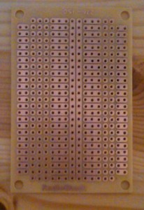
I spent an embarrassingly long time trying to figure out which perfboard to use. A garden variety perfboard has one solder pad per hole. Two additions I wanted were a power strip or power bus as part of the board, and pads designed for an integrated chip (IC) where the pad next to each chip pin was electrically connected. The first option avoids soldering multiple components to one Power In, and the second allows for simpler connection of IC inputs and outputs. An example of a perfboard that has both these options is shown below:
This is a beautiful board, but it was too small for my project. My ICs were also too wide to work exactly with this layout. And my screw terminals at the edge could not make use of the nice connected pads because they themselves are two holes deep. So I hunted around for a larger version of this board and it was surprisingly difficult to find.
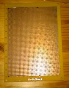
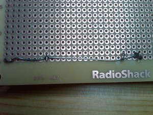
My pad-per-hole perfboard was the right size, so I decided to move ahead with that. And based on an obscure tip in an internet forum, I was able to figure out how to add a power bus to basic perfboard. That is the trick I will show here. It is very simple. Take a piece of solid insulated wire, the same stuff you are using to connect the components, and strip it completely. (You can also use bus wire, but with a decent pair of wire strippers there is no reason to spend extra for a new spool of wire.) Solder it in underneath the perfboard at two points, running along one row or column and there you go — you have a power strip. The only difference is that you must attach components to the wire in addition to or instead of the pads.
Here is a perfboard with two power strips attached:
Connections are made like this:
Because the power strip is not insulated, it is probably a good idea to cover it with electrical tape once you are finished soldering.
Here is a view from the top. The sockets for the M5451 and the Arduino Mini Pro are visible.
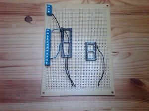
Automated LED stair light circuit starts to take shape. IC sockets and screw terminals are installed and ground wires connected.
This still doesn’t solve the IC connection issue, but one traditional solution is to run the wire in the hole next to the IC pin and bend the lead down to connect with the IC pin. I will be doing that. The other option I’m aware of is to connect adjacent pads with solder, but I have not had good luck heating pads too directly. It’s all too easy to burn them off.
I am planning to complete perfboard soldering today with the exception of the fuse, the fuseholders I ordered were the wrong mount so I need to wait for new ones to arrive.
LED stair sensors and other progress
I’ve received a few comments and e-mails about the LED stairs lately, and I want to thank everyone who took the time to contact me. Although I haven’t posted in a while, I have been moving forward with the project. When it is complete I plan to publish a full list of materials and schematics so others can make their own.
The next step has been to add the sensor that will detect when someone is on the stairs. I decided to go ahead and cannibalize Robie’s PING))) ultrasonic sensor, partly because Robie sadly did not survive the kids playing with him, and I am already familiar with the PING))) library for the Arduino.
There are probably good alternatives for this sensor in terms of price or function (it costs about $30, so two of them is certainly an expense). I have noticed one quirk with the PING))). If there is no object in front of it within a few feet, taking a reading is noticeably slow. It will wait until the sound wave has bounced back. This can mean that a fast moving foot will not trigger the sensor. I have not yet tested if the opposing stair wall is close enough to get around this, but my feeling is that it won’t. I’ve decided to look at this as a feature, not a bug. I don’t always want to trigger the sensor; during the daytime, for example, lighting up the stairs is unnecessary. This way I can simply start the sequence by placing my foot on the bottom or top stair for a moment, and bypass it by default.
I’ve written and tested the code for the upward sweep of lights. At present, this is not too fancy; they turn on one by one, starting with the bottom step and going to the top. There is a pause, then they turn off one by one starting at the bottom. The downward sweep will be the same in reverse. The beautiful thing about using the Arduino is that I can easily reprogram the light sequence if I get bored! I could even make it do random variations.
I’ve gotten the other mundane things I need to install everything. The second sensor, a grounding strip, bell wire, etc. I managed to misplace the thin aluminum sheet for mounting the PING)))s so I need to get to HacDC and scrounge, or go to the hobby store (again).
I have the perfboard ready for permanent soldering. Then the next step is drilling holes in walls. I’ve been a little nervous about this, I won’t lie. But as install jobs go, this should be straightforward. The back of the stairs is immediately above the unfinished part of our basement, so all I’ll need to do is drop the wires down. I have a wall snake but I may not even need it.
LED stairs: the chips are talking
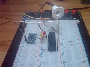
In my last post on the LED stairs, I discussed using the Arduino and an M5451 driver chip to control the lighting sequence. Today, I completed my first breadboard version:
The Arduino Mini Pro is on the left and the M5451 is on the right, positions I will reverse in the final design. I used LEDs that I happened to have on hand so it looks a little odd. The large one with the white shield, towering over the others, is the type I plan to use on the stairs. It is a NorthStar NS 20 CW 20° LED Fixture.
I used the Lightuino source code to make the Arduino talk to the M5451. My needs are fairly simple, I just want the lights to go on one by one, then turn off after a delay. For the most part I was able to get what I needed from the begin_here3 sketch included in the Lightuino. However, the Lightuino is designed to control 70 individual LEDs (it has two M5451 chips, each chip can handle 35 LEDs). The code uses a byte array of length 9, where each element has 8 bits, each bit turning an LED on and off. This is pretty simple, but the addressing is very odd. I would have expected the first element of the array to control the first 8 output pins of the M5451. It does not — instead, given pin 0 in the upper left, it starts from the output pins in the lower left and goes backwards. Once I figured this out, the code became very straightforward. (I will be posting my code once the project is complete.)
The only real difficulty I experienced today was in getting the chips to sit squarely on the breadboard and make a solid electrical connection. I soldered in header pins for the Arduino Mini Pro and I think they were not perfectly straight (though extremely close) and that was enough to cause a problem. The needlenose pliers came in handy. For the M5451 I had a socket, and that too had problems fitting in, not caused by my soldering! Pliers and pressure came to the rescue in that case. For programming the Mini Pro I just put some male headers on the FTDI cable and held it in the right place, no soldering — and to my surprise, that worked quite well.
I have spent quite a lot of time ensuring that the design will be as fireproof as possible. I rarely see this issue discussed in the designs I’ve seen, but a house fire is the most dangerous side effect that can happen from an electrical project. Of course we are talking fairly low voltages and currents, and maybe that is why people don’t worry as much. I spent a long time on this step and talked to a lot of people at HacDC, and maybe I overthought it. At any rate, here is what I came up with, and maybe it will help someone else:
For in-wall wiring, I chose this bell wire. It is UL class 2 rated for up to 300V, and the description says it all: “Low voltage cable with insulated solid conductors resistant to spread of fire.” This is a safe and economical option. Other options I came across were speaker wire (overpriced for my needs — I don’t need a clean signal protected from interference) and ethernet cable (didn’t like the idea, and the wire gauge is smaller, not an improvement).
For wire-to-wire connections, I will use wire nuts. Because of the low voltage involved, I do not need to make the connections in an electrical box.
The room where the controller will sit does not have a power socket — it is an unfinished part of our basement. This is very convenient for running wires, but I will need power. I looked into installing an electrical socket myself, and it is certainly common for homeowners to do most of this followed by a certified inspection afterwards. But, for now I will just run an extension cord from the other room.
Robotics Open House at the University of Maryland
Last Friday the University of Maryland had an open house for their robotics department. This was a free event, including lunch, and very well organized. I had not been able to go to any previous robot competitions at the university so I was eager to see what they had.
The university has 18 robotics labs, 16 of which were open for tours. They spend approximately $15M per year on research.
The day started with a keynote presentation by iRobot, best known as the inventors of the Roomba, a robot that can vacuum your home. This device has sold in the millions. But the most interesting part of the talk centered on various military projects, where sales of a few thousand are considered highly successful. iRobot is working on mine detection robots and robots to help sample and clean up the Gulf oil spill. Lots of cool videos. They were a little spare on details, but all I can say is that it looks like a fun place to work.
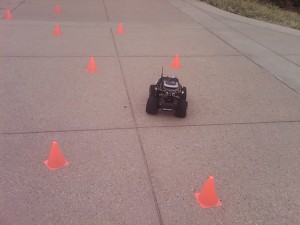
The first tour I took was on the plaza of the engineering building. There were several robots navigating their way around some orange cones.
I was familiar with this layout, because a group I was involved in submitted an entry for this competition. The university robots were pretty impressive and I was not surprised to hear that they had won last year. Here is a close up:
This used a Tamiya platform, which the speaker did not recommend (he said Emaxx would have been better), with a small computer and wireless router sitting on top of the chassis. Like Robie this fellow sported several PING))) sensors. (See my Facebook album for more photos.)
Next up, I had seen a blurb for flying robots controlled by brainwaves. This was too good to miss. The traditional media agreed with me — a cameraman from Channel 9 was there. (He even asked me a few questions, though I don’t know if I ever made it on air.) As it turned out, the brainwaves were a small part of the control system. A standard remote-control setup did most of the work. But control of the altitude or the yaw could be turned over to a human subject wearing a headset that does a primitive EEG. By concentrating, the subject could change his brainwaves in one direction or another. This is a monotonic control function, and so, can’t really do much. The goal is to be able to send the robot somewhere by looking in a particular direction…don’t know if they can do this with brainwaves alone as opposed to eye tracking, but it’s an interesting idea.
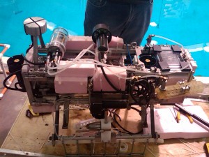
Another highlight was the Neutral Buoyancy Facility. This is a three-story building with a giant water tank occupying the center. Underwater robots swooped and dived as we watched. The facility can be used to design underwater robots and to simulate the weightlessness of outer space.
The robot shown here is Tortuga 3, which has won a number of important competitions. It was not running today, however, because the on-board computer was showing a disturbing tendency to shut down unexpectedly. The thrusters still continue to function in that case, which can lead to an irreversible dive. (Sounds like a design flaw to me.) This allowed us to take a closer look at the fascinating machine. Building a land robot is pretty hard; making one that is waterproof too is very impressive.
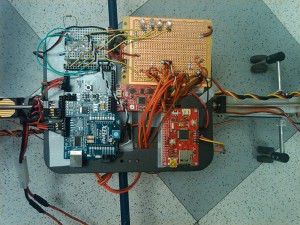
Finally, here is a close-up show of componenets used in a tandem helicopter. They will look familiar to many hobbyists: SparkFun, XBees, and RadioShack perfboard. It is heartening to feel a kinship with cutting edge research.
All in all it was a great day and the price couldn’t be beat. For more photos and details about the visit, please see my Facebook album.
Expanding the Arduino: cheap ways to add output pins and power
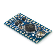
For the LED stairs, I need to control 14 LED lamps and 2 sensors. From the beginning, I had in mind an Arduino as the microcontroller for this project. Although it is possible to do a primitive version of these stairs without a microcontroller, having a brain at the center gives many more options. And a basic Arduino is (relatively) inexpensive. The Arduino Pro Mini, which I am planning to use, is only $19.
The Pro Mini has 14 digital input/ouput pins. Each output pin can produce 5V and up to 40mA. This is more than enough for a single LED. But I will be using LED lamps that require 12V. We don’t have enough power.
Antoher issue: these pins need to control all the LED lamps plus the sensors. And if you want to do any debugging, 2 of them need to be reserved for serial communication. We don’t have enough pins.
I was able to come up with solutions to these problems. It occurred to me that the need for “more pins, more power” must be a pretty common one for micrcontroller projects in general and this might be useful for other people to know.
How to add output pins
The simplest way to increase the number of ouput pins is just to buy a bigger board. The Arduino Mega provides a whopping 54 output pins. But it will cost you: the Mega is $50. And unlike the basic Arduino, you are limited in your choices regarding form factor and input power. It’s big with lots of deluxe options and that’s what you get.
The way around this is to use the Arduino to talk to another chip, called a shift register. An example of this is the 74HC595. The Arduino takes a few pins to talk to the shift register, which has 8 output pins of its own. The Arduino tells it which ones to turn on and off. Even better, the shift registers can be daisy chained so that one Arduino can talk to multiple shift registers without using any more Arduino pins.
This does increase programming complexity because the Arduino must talk to the shift register in a specified protocol. Fortunately, there is code out there that other people have written (this is the nice thing about using a popular platform). There is an excellent tutorial on the Arduino site called ShiftOut. There is a lot of stuff on the the site but it can be very hard to find, and that was true here.
As for cost, a 74HC595 will cost $0.35 or less…much cheaper than upgrading to a Mega!
How to increase output power
I already knew the answer here: add a transistor. The output pin switches a transistor which can be used to carry much greater current and voltage. The question is, the best way to implement this. I already had a painful experience in building my Speed Vest. In order to drive the electrolumincescent wire, it was necessary to switch high voltage, AC power. For that project I blindly followed the authors’ design and soldered 13 triacs in point-to-point wiring on an Arduino shield. That was not an experience I wanted to repeat.
Integrated circuits are all about packaging transistors together, right? I should at least be able to find a chip where they shared a common input voltage and ground, which would reduce the number of connections required by a factor of 3. And if it includes the protective diodes, even better. There is a famous chip that does this, called the ULN2803A. It has eight Darlington array transistors and is designed to be controlled by the 5V logic the Arduino uses. Since there is one pin for each transistor, no programming is required.
For a nice overview of this topic, see this article on using microcontrollers with switching transistors.
Cost of the ULN2803A? I got it at Arrow for $0.51.
Doing both at once
So far so good. We could take care of everything by adding 2 shift registers and 2 Darlington arrays. Pretty good but more components than I’d like. Is it possible to find a chip to do both tasks at once? Yes.
More knowledgable readers may already be wondering about LED matrix drivers. Using an Arduino to talk to sets of LEDs is a very common task and there are no shortage of articles on this. There are some nice libraries that have been developed too. In general they were not suitable for this project because despite the word “LED” I am seeking to drive higher power devices — LED lamps. Also, the matrix paradigm imposes certain requirements as far as connections and addressing that weren’t relevant here and that I preferred to avoid.
Eventually though I found the right kind of LED driver: the M5451. It can handle 12V power and can control 35 devices with a unified brightness control. Although the brightness control isn’t required here, it is a nice feature; the right type of signal — pulse-width modulated — can extend the life of the LEDs.
Next step, find code that allows the Arduino to talk to the M5451. (I am not that interested in writing device drivers.) Fortunately this chip is used by the Lightuino, which is an open-source project that (with some modification) has the code I need.
Cost of the M5451 (also listed as MM5451 at some suppliers): $3.15.
Although the M5451 should do everything I need, I’ve ordered the other two chips as well just to see how each option works. I suspect they will be useful for future projects too. Can’t wait until everything shows up and I can start breadboarding!
Automated LED stair lights
I’ve been hunting for a new project to do ever since completing my contest entry for Robie. I’ve done a number of interesting small things, mainly with the kids, but nothing too big. Then recently Make: Online featured this:
When someone walks on the first step, the LEDs light up in sequence. Aside from looking cool, this is a great safety feature. I have had more than a few times where I have stumbled on stairs in the dark. Although we have convenient overhead lighting for most of them, I can be reluctant to use it, especially if the kids are asleep upstairs.
The only problem with this video is that there are no technical details. There is a website, which features the video, but no information.
There is a stairway LED lighting Instructable with more details. This is a simpler version, and less good from my perspective. The wires are all visible. Only the left side of the stairs is lit. And the artistic delay between lighting each stair is gone. It does provide a basic framework and that is helpful. I have learned that presentation is 80% of the oomph factor in these projects — so, we need to upgrade.
Looking very carefully at the video, we can figure out a few things. The LEDs and the sensor are all on one side of the stairs. Both sides of the stairs appear to be lit because the focused light from one side is bouncing off the white wall. The LEDs are set into metal plates that sit in the wall. There is a sensor that sits on the bottom stair, the same side as the lights; there is no receiver on the other side. The sensor appears to have two openings, which would be consistent with ultrasonic, but I can’t be sure of that. When the sensor is triggered, the stairs light up in sequence. After a fixed amount of time, they turn off in sequence, even if the sensor at the opposite end is not triggered.
I will need to cut into the wall to achieve the same look. I have done this before, but not often. I will also need to run wires in the walls. That, I have never done. In fact, I’ve never seen anyone else do it either. A little research on running wires revealed that the key tool is fish tape, a reel of flexible steel rod that can be guided through the wall with a wire attached. I always like to buy more tools so am now the proud owner of this:
Since I am only dealing with one wall and do not have to go between floors, I think this is a manageable project. My husband was fairly calm about my wanting to put holes in the wall. He suggested that I start with the basement stairs first for practice. A reasonable idea.
The Instructable stairs use two timer chips to operate. I plan to use a microcontroller for nicer effects, probably one of the Arduino Pro Minis that I recently ordered.
Next issue, the sensor. I have a PIR sensor lying around that could be used. I am a little concerned that it will have too broad an angular detection range. I only want the sensor to trigger if someone steps on the bottom stair, not walks in front of it. I could also cannibalize Robie’s PING))) ultrasonic sensor, though running that continuously would probably increase power consumption. (A quick glance at the specs shows PING))) current requirements of 20mA, while PIR is >3mA.) The Instructable uses IR, but that requires elements on both sides of the stairs. I only want to run wires in one wall! The author mentions that IR sensors work well here because they don’t trigger in daylight. That’s a nice feature, and to get it with a different type of sensor I will need either a timer or a photocell. Probably a photocell, that is simpler and I have bags of them lying around from my line-following robot project.
The biggest unknown are the LEDs. I don’t know what model they are. I want them to be powerful enough to give off good illumination and reflection. I would very much like to stay within the world of battery power. If 120V are needed I don’t think I will comfortable running that type of wiring. As it is I will need to learn the applicable electrical code. And, it would be nice if they came in a suitable wall mount. Time to do some research.
